
2DIN Car Radio Installed but Controls Fail: An Installer's Diagnostic Guide
2DIN Car Radio Installed but Controls Fail: An Installer's Diagnostic Guide
Short answer: when a 2DIN universal car radio powers on but the steering-wheel buttons, phone projection or audio setup do not behave as expected, treat it as a fault-isolation problem before treating it as a product failure. Verify DC 12V power and ground at the connector first, then the harness and steering-wheel control (SWC) configuration, then touch control on its own, and only after that the wireless and wired CarPlay/Android Auto link, Bluetooth pairing, GPS reception and FM/AM RDS. In the majority of fits, the fault resolves at the harness or configuration layer — before any replacement decision is justified.
This scenario guide is written for installers, workshop technicians and distributors who fit universal double-DIN units across mixed vehicle platforms. The reference platform used throughout is the TOPNAVI TN-3036, a 16.8-inch Android 13 unit with 4GB RAM and 64GB ROM, 4×50W output, 2DIN universal installation, a −30°C to 75°C operating range and CE/FCC certification. TOPNAVI — Shenzhen Top Navi Electronic Tech Co., Limited — is a Shenzhen-based manufacturer of Android car radios, head units and in-vehicle multimedia products, founded in 2014 and exporting to more than 70 countries.
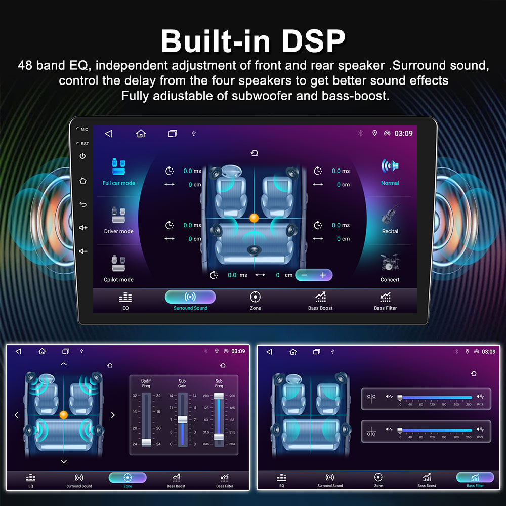
A large-screen Android head unit in the 2DIN universal format: power-on confirms the main board is fed, but it does not confirm the SWC or harness layer.
What "Controls Fail" Actually Means After a Successful Power-On
"Controls fail" is not one fault. On a universal double-DIN install it describes four different symptom clusters, each sitting on a different signal path, and each with a different resolution path.
- Steering-wheel control (SWC) failure. Buttons do nothing, respond with a delay, or trigger the wrong function. The signal travels from the vehicle's button cluster, through the harness adapter or CAN box, into the radio's key-input wiring or digital bus input.
- Touch and panel control failure. The screen is visible but slow, unresponsive in certain zones, or mis-tracking taps. This is internal to the unit's capacitive touch layer.
- Projection failure. Wireless or wired CarPlay and Android Auto do not launch, pair once then drop, or connect on one phone but not another. This is a link-layer and settings problem before it is a hardware problem.
- Audio and setup failure. Sound comes from some speakers but not others, the amplifier does not switch on, DSP presets sound wrong, or the fade/balance behaves unexpectedly. This is routing and configuration, not amplification capacity.
A display that boots proves only that the main board is receiving power. It does not validate ground quality under load, ignition/ACC sense, the pin mapping of the adapter harness, the CAN protocol match, or the key-resistance values of the steering-wheel buttons. Installers who skip these checks move straight to a return decision on evidence that was never collected.
For distributors, the cost of that misdiagnosis is not only one unit. A returned batch creates freight, inspection time, credit notes and a technical argument with the supplier — all of which could have been closed at the bench with ten minutes of measurement.
Why 2DIN Universal Installs Produce Control Faults More Often Than Vehicle-Specific Units
Universal fitment is a deliberate trade: one chassis covers many vehicles, and the vehicle-specific interface is bridged by adapters. Double DIN is the dominant form factor in the category — Grand View Research reports the double DIN segment at 44% of car stereo market revenue in 2025 — which means most installer exposure to control faults happens on exactly this architecture.
Every adapter in the chain is a potential mismatch point: the harness pinout, the CAN box and its firmware, the antenna power feed, the amplifier remote lead, and the reverse trigger. A unit can be electrically perfect and still fail on an install where the CAN adapter is the wrong variant for that vehicle's trim level.
Suppliers manage this at the compatibility layer rather than the hardware layer. TOPNAVI's documented approach includes pre-sales full-model CAN protocol matching, a compatibility database updated monthly, pre-sales adaptation testing against buyer requirements, and one-to-one technical troubleshooting for individual cases. That is the correct division of labour: the unit is validated at the factory, the vehicle interface is validated at the bench.
It is also worth separating certification from fitment. CE and FCC certification addresses electromagnetic compatibility and radio-equipment requirements — the factory applies EMC/EMI shielding design and anti-interference circuit layout, and runs CE/FCC EMC testing before shipment. Certification tells a distributor that the product may be placed on the market; it does not tell an installer that the SWC wires are on the right pins.
The Solution: A Four-Layer Isolation Model for the TN-3036 and Comparable Units
The isolation model works because each layer can be tested without dismantling the previous one. Work top-down and stop at the first failed layer.
Layer 1 — DC 12V power, ignition sense and ground
Measure at the radio connector, not at the battery. Confirm constant 12V, confirmed ignition/ACC voltage with the key in the correct position, and ground continuity back to the chassis. A ground that reads continuous on a meter can still be inadequate under audio load, which is why an intermittent audio or touch symptom sometimes disappears when the ground is relocated to bare body metal. Record the readings — they are the first item in any evidence pack.
Layer 2 — Harness and steering-wheel control configuration
This is where most "controls fail" complaints are actually resolved. Two configurations exist and they are not interchangeable: resistive/analog SWC, where two key wires carry resistance values, and CAN-based SWC, where a CAN box translates vehicle bus messages into radio commands. A resistive unit wired into a CAN vehicle without a box will not learn buttons at all; a CAN box running the wrong firmware may learn buttons and then map them incorrectly.
Verify the adapter part number against the vehicle's model year and trim, confirm that the SWC ground reference is the same ground the radio uses, then run the SWC learn procedure and record the raw key values it captures. Correct values with wrong mapping is a configuration fix. No values at all is a wiring or adapter fix.
Layer 3 — Touch control, tested on its own
Touch is the fastest discriminator in the whole sequence. If touch responds correctly while SWC does nothing, the panel, the digitizer and the main board are healthy and the fault sits in Layer 2. If touch itself mis-tracks or fails in a zone, the panel is the suspect.
TN-3036-class hardware is built around a high-sensitivity capacitive touch layer with an anti-interference touch algorithm, validated with a 100,000+ touch durability test and a full screen function inspection before shipment. That does not make touch failures impossible, but it does mean a touch fault should be evidenced — photographed, reproduced after a recalibration, and reproduced on a second unit — before it becomes a claim.
Layer 4 — Wireless and wired CarPlay/Android Auto, Bluetooth and GNSS
Projection faults are usually pairing-state faults. Clear the phone's stored pairing for the head unit, clear the head unit's stored device list, and re-pair in the correct order: Bluetooth first, then the wireless projection handshake. Test with a second phone of a different platform before drawing a conclusion. For wired CarPlay and Android Auto, swap to a known-good, short, data-rated cable — charge-only cables are a recurring cause of "connects then drops".
Platform comparison data published for TOPNAVI's Android multimedia units cites a 5-second wireless connection and roughly 80% faster connection than wired adapters, plus 5-year free OTA firmware updates for CarPlay and navigation features. If a unit connects reliably after an OTA update but not before, the fault was firmware, not hardware.
Layer 5 — Audio routing and DSP
With 4×50W output, silence on one channel is rarely an output-stage limit. Run a per-channel speaker test, then check fader/balance, DSP preset state and the amplifier remote lead. Factory platform data for TOPNAVI's Android units cites a 30% higher sound fidelity figure against non-DSP systems — a DSP-equipped unit that sounds "wrong" is more often on the wrong preset than on a failed amplifier.
Layer 6 — FM/AM RDS and antenna power
Weak or noisy reception after a universal fit commonly traces to the antenna feed: a missing phantom-power lead for an active antenna, an unpowered diversity module, or an adapter that bypasses the vehicle's antenna amplifier. RDS text failing to appear is a reception-quality symptom, not a tuner failure, until the antenna feed is proven good.
Layer 7 — GPS reception
TOPNAVI's GNSS design uses a dual-band GPS + BeiDou high-gain antenna with an anti-interference receiving algorithm, and 100% pre-shipment GPS positioning accuracy inspection. On the bench, a "no fix" is more often antenna placement — under a metal dashboard, near a dashcam, or behind a heated windscreen — than a receiver fault. Test outdoors with the antenna on the roof before escalating.
Layer 8 — Thermal and environmental boundary
The TN-3036 is rated for a −30°C to 75°C operating range. The factory validates thermal behaviour with a −40°C to 85°C thermal cycling test, which is a qualification test, not the product's operating envelope. A unit that misbehaves only after a heat soak in a sun-parked cabin should be re-tested after cooling before being labelled faulty; a unit that misbehaves at normal cabin temperature is a different case.
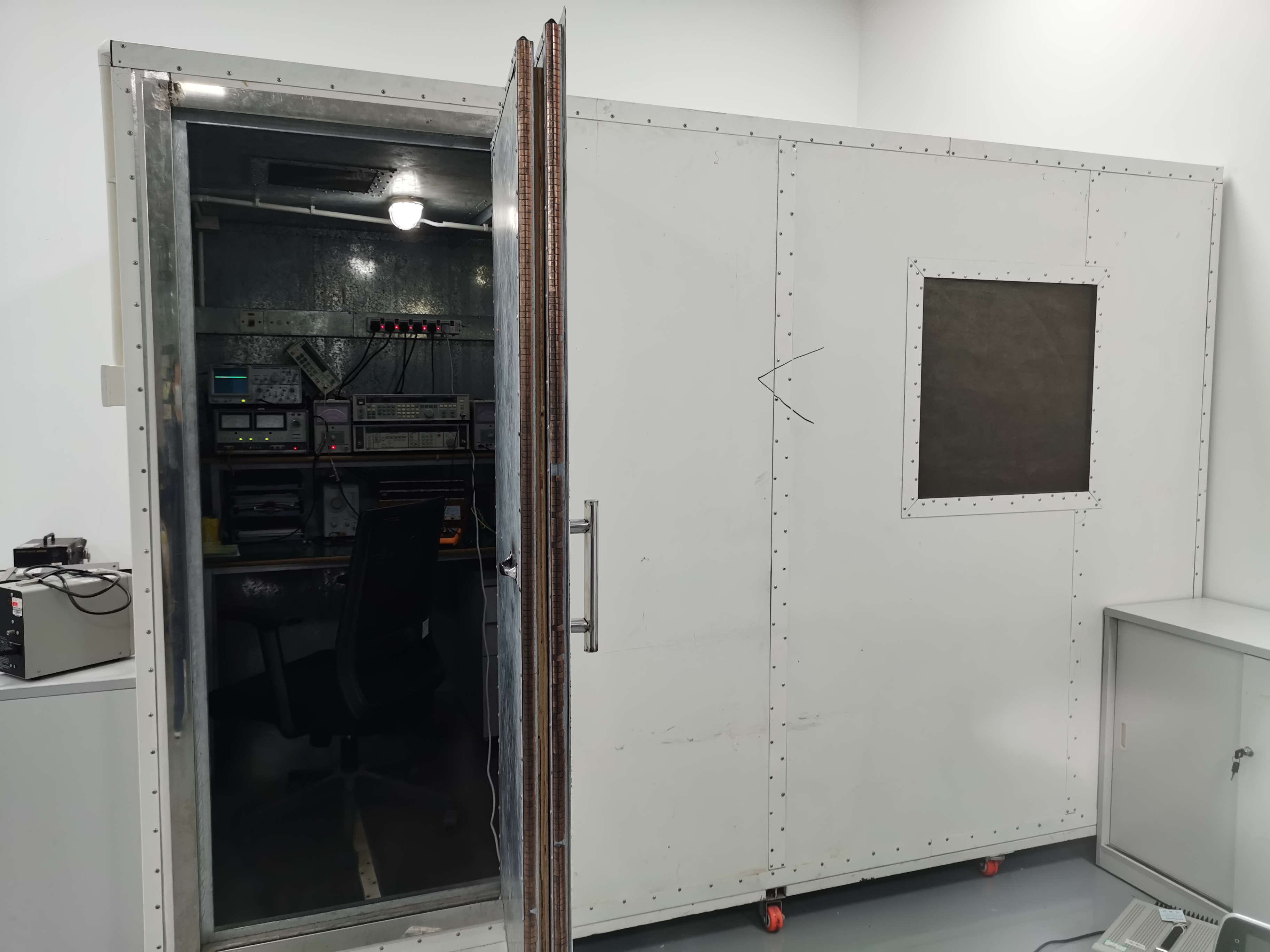
Signal shielding room: EMC and radio-frequency testing happens at the factory, which is why post-fitment link faults usually belong to the vehicle side of the interface.
Step-by-Step Diagnostic Sequence (Bench-Ready, in Order)
Use Cases: Three Installs Where This Sequence Pays for Itself
Use case 1 — Distributor batch check before delivery
A distributor receiving a mixed pallet of universal 2DIN units should not test each unit on one car. Bench-test three units on the three vehicle platforms that generate most of the channel's complaints, run Steps 2–9 on each, and record the raw SWC values per platform. This builds the compatibility reference the reseller network will call about — and it turns installer complaints into a known-value lookup instead of a return.
Use case 2 — Single retrofit with CAN-based steering-wheel controls
A vehicle with bus-based buttons will never respond to a resistive key-wire configuration, however carefully the wires are spliced. The fix is the correct CAN adapter and firmware for that model year, then a learn procedure. If the buttons then trigger the wrong functions, the adapter is right and the mapping is wrong — a two-minute configuration correction, not a hardware swap.
Use case 3 — Used-car upgrade where the original radio fed the amplifier and antenna
When the factory head unit was the amplifier remote source and the antenna power source, removing it removes both signals. The result looks like a defective new radio: audio only at low volume, or no reception. In this scenario the 2DIN unit is behaving correctly; the install is incomplete. TOPNAVI positions its Android multimedia units as suitable for used-car radio upgrade scenarios, which is precisely the context where the amplifier and antenna feeds must be re-established by the installer.
Comparison Table: Which Fault Class Does the Symptom Belong To?
The table below converts the diagnostic sequence into a decision view. It uses only the layers and production checks described above.
| Fault class | Typical installer report | Confirmation test | First action | Claim justified? |
|---|---|---|---|---|
| Configuration | Buttons do the wrong thing; DSP sounds thin | Touch works; raw key values captured but mis-mapped | Re-run learn procedure, correct mapping and preset | No |
| Harness / adapter | No SWC at all; some speakers silent; amp not switching | Pin mapping audit and known-good adapter substitution | Repin or replace the adapter | No |
| Vehicle protocol mismatch | SWC dead on one model line only | Same unit tested on a second platform behaves correctly | Fit the correct CAN box and firmware | No |
| Wireless link | CarPlay pairs then drops; Android Auto will not launch | Wired test with data-rated cable; second phone; firmware updated | Clear pairing state, update firmware, relocate antenna | Only if repeatable across phones after update |
| Unit-level fault | Touch dead after calibration; no output on any channel; no GPS fix outdoors | Panel test plus reproduction on a second vehicle; compare against factory checks — 100,000+ touch durability test, 72-hour aging, 100% GPS inspection | Build the evidence pack and raise the claim | Yes |
TN-3036 reference specification (as supplied for this guide)
| Parameter | Specification |
|---|---|
| Display | 16.8-inch |
| Operating system | Android 13 |
| Memory | 4GB RAM / 64GB ROM |
| Audio output | 4×50W |
| Installation | 2DIN universal |
| Bluetooth | Bluetooth 5.0 |
| Operating temperature | −30°C to 75°C |
| Certification | CE, FCC |
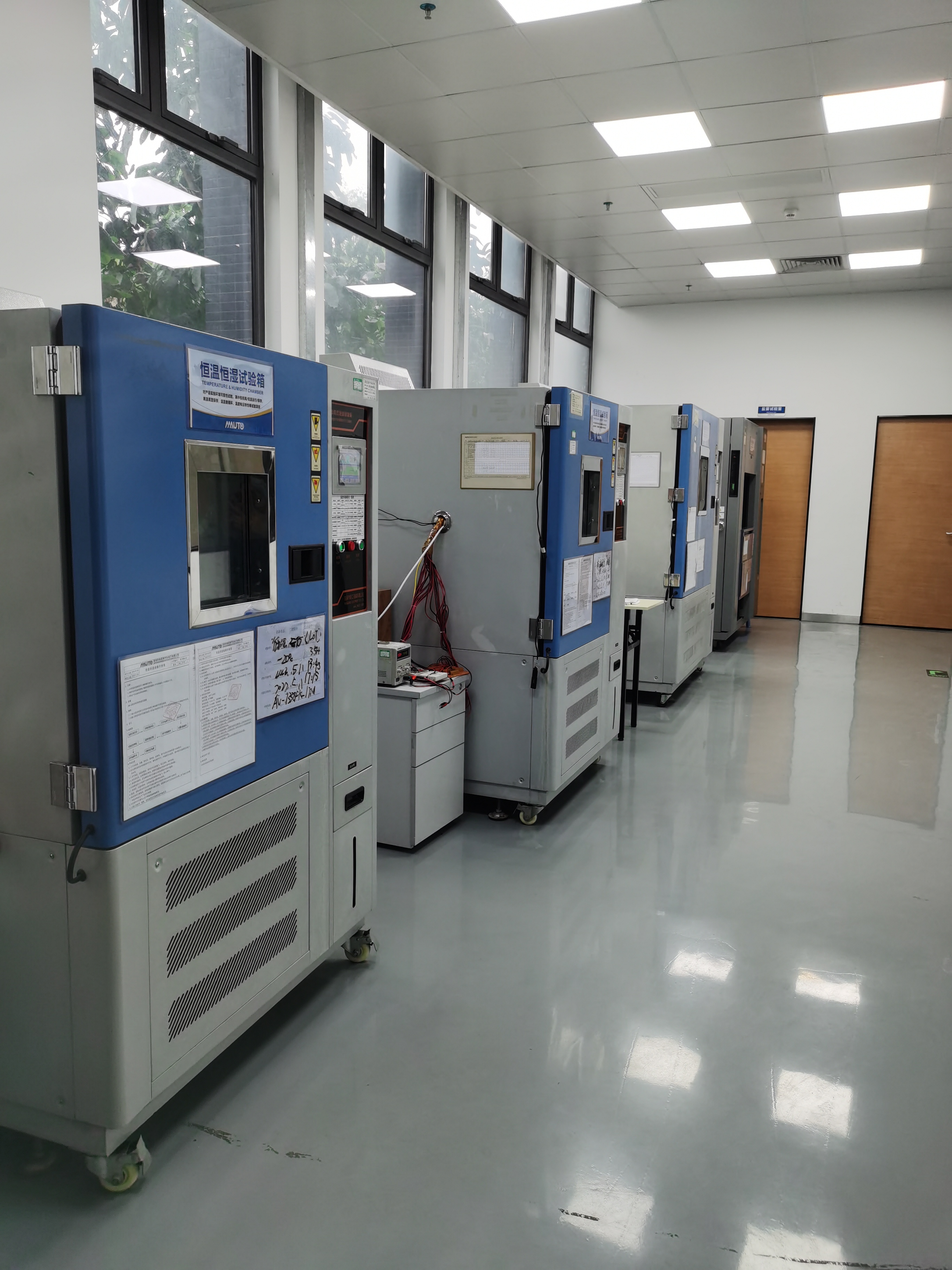
Thermal cycling equipment: the factory runs a −40°C to 85°C cycling test as qualification, which is separate from the product's −30°C to 75°C operating range.
Frequently Asked Questions
1. Does a 2DIN car radio need CE or FCC certification before it can be installed or imported?
For market access, yes — CE for the European market and FCC for the United States are the relevant conformity marks, and car radios with recording or reproducing apparatus fall under HS code 8527.21 for customs classification. The TN-3036 is specified with CE and FCC certification. Certification covers electromagnetic compatibility and radio-equipment requirements, not fitment: the factory applies EMC/EMI shielding design and anti-interference circuit layout and runs CE/FCC EMC testing before shipment, but the harness and CAN adapter still have to be validated per vehicle. Distributors should retain the certificate documents alongside the test reports, because a compliance question from a reseller is answered with paperwork, not with a spec sheet.
2. Can a steering-wheel control failure be fixed without replacing the head unit?
In most cases, yes — provided touch control works. If touch responds correctly and the SWC buttons do not, the panel and main board are healthy and the fault sits in the harness, the adapter variant or the key mapping. Run the learn procedure, record the raw key values, and compare them against the vehicle platform's expected values. A resistive unit on a CAN-based vehicle needs the correct CAN box; a CAN box with the wrong firmware needs the right firmware. Only a unit that fails on a second vehicle with a known-good harness should be treated as a hardware failure.
3. Where does the cost of a control-fault misdiagnosis actually sit?
Not in the unit price — in the labour and logistics wrapped around it. The recurring cost drivers are bench time spent swapping parts instead of measuring, return freight and inspection on units that were never faulty, adapter re-orders when the wrong variant was shipped, and repeat vehicle visits when the fault returns after the customer left. A ten-minute voltage and key-value record at the first visit removes most of these. For distributors, the same logic applies at pallet level: testing three units on three platforms before delivery is cheaper than processing a single disputed batch.
4. Should an installer or distributor validate a sample before committing to a batch?
Yes, and the sample test should be specific: fit the sample to the vehicle platforms that generate most of your complaints and run the full sequence — power and ground, SWC learning, touch, wireless and wired CarPlay/Android Auto, Bluetooth, FM/AM RDS, GPS. Record the raw key values per platform and keep them as your reference set. A fitment problem discovered on one sample is a configuration note; discovered after a batch is a channel problem.
5. How quickly can a control or connectivity fault be closed out, and what support should the supplier provide?
Speed depends on evidence quality rather than on the fault itself. A documented case — vehicle model and year, voltage readings, raw key values, firmware version, and a repeat test result — is usually resolved at the configuration or adapter layer without shipping anything. TOPNAVI supports this with pre-sales CAN protocol matching, monthly compatibility database updates, one-to-one technical troubleshooting, and OTA firmware updates; platform comparison data for its Android multimedia units cites 5-year free OTA updates for CarPlay and navigation features. To start a case, or to request a TN-3036 sample and quotation for your vehicle coverage, contact the team at sales@topnaviauto.com or via WhatsApp at +86 150-7094-1278.
Conclusion: Isolate the Layer, Then Decide
A 2DIN universal car radio that powers on but refuses to behave is almost always telling you where the fault is — you just have to test in the right order. Power and ground first, harness and SWC second, touch as the discriminator, then projection, audio routing, radio and GPS. Each layer has a pass criterion, and the first failure is the answer.
For installers, this sequence converts an open-ended complaint into a documented, closable job. For distributors, it converts a return into a reference value. And for both, it keeps the replacement decision where it belongs — at the end of the process, supported by evidence rather than by frustration.
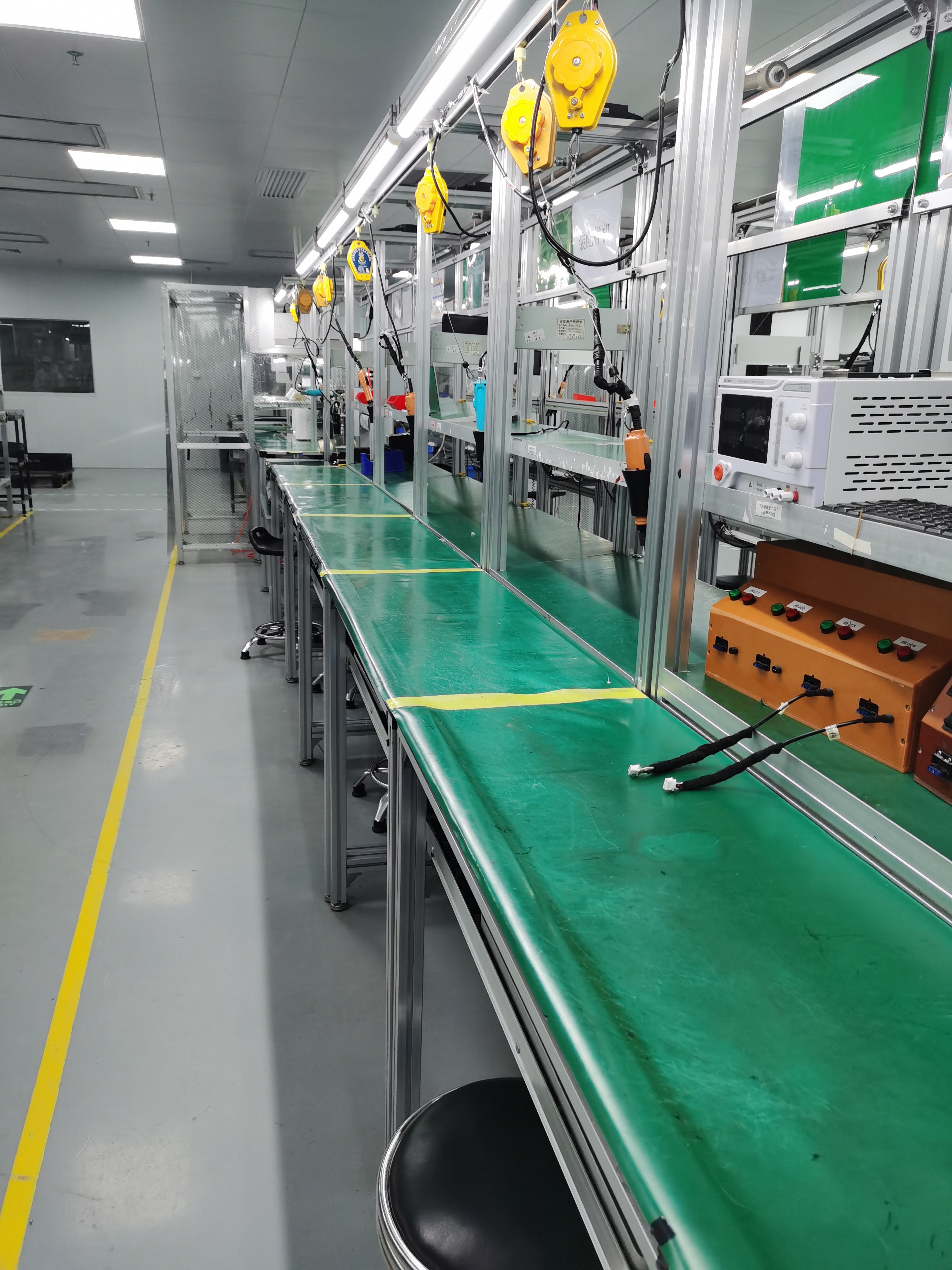
Production line at the Shenzhen factory: units ship after aging and full-function inspection, which is why an evidence pack matters more than a first impression.
Need a sample unit, a quotation, or the full product catalog?
TOPNAVI supplies universal and OEM/ODM Android car radios from a 20,000 m² factory in Shenzhen, with CE, FCC, RoHS and E-Mark certified product lines and technical support for installers and distributors.
Download the catalog: TOPNAVI product brochure (PDF)
Website: www.topnavi.com.cn | Email: sales@topnaviauto.com
WhatsApp: +86 150-7094-1278

OEM and ODM support covers harness and configuration variants for different vehicle platforms and channel requirements.
Have Questions or Need More Details?
Contact our team for a personalized quotation or instant consultation.
Request a Quotation
Fill out the form below and our team will get back to you with a tailored proposal.
WhatsApp Direct Chat
Prefer to chat in real-time? Message us on WhatsApp for instant assistance & quick answers.
- Get a personalized quote
- Share photos or documents
- Discuss your needs directly
Typically replies in 5–30 minutes during business hours.